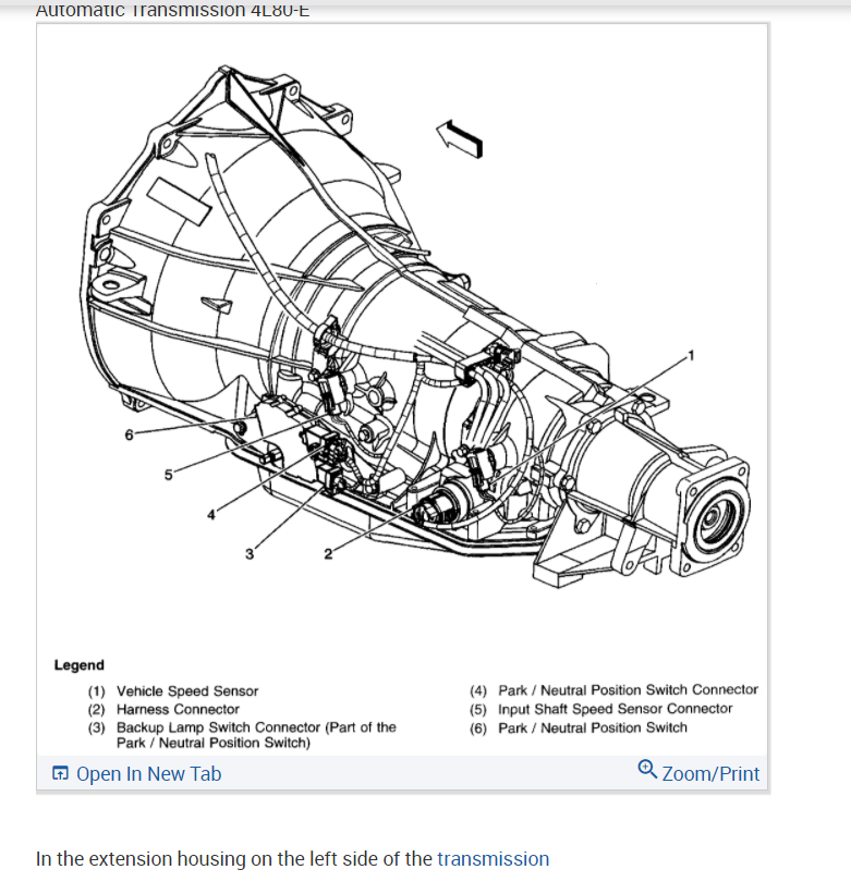
Automatic Transmission 4L60E Transmission Cooler Lines Diagram
4L60E Transmission Wiring Diagram Wiring Diagram
Buy Transmissions Problems Wiring & Diagrams 4l60e Transmission Exploded View Diagram Related Posts 4l60e Valve Body Diagram 4l60e Valve Body Identification Guide 4l60e Mechanical Components Diagram Previous Article 4l60e Bellhousing Bolt Pattern Diagram Next Article What Causes A 4l60e Transmission To Slip
Chevy 4l60e Wiring Diagram 2003
View 4l60e transmission cooler line diagrams that route to the radiator and to an external transmission cooler. Read More 4l60e 4l60e Transmission Guide & Information
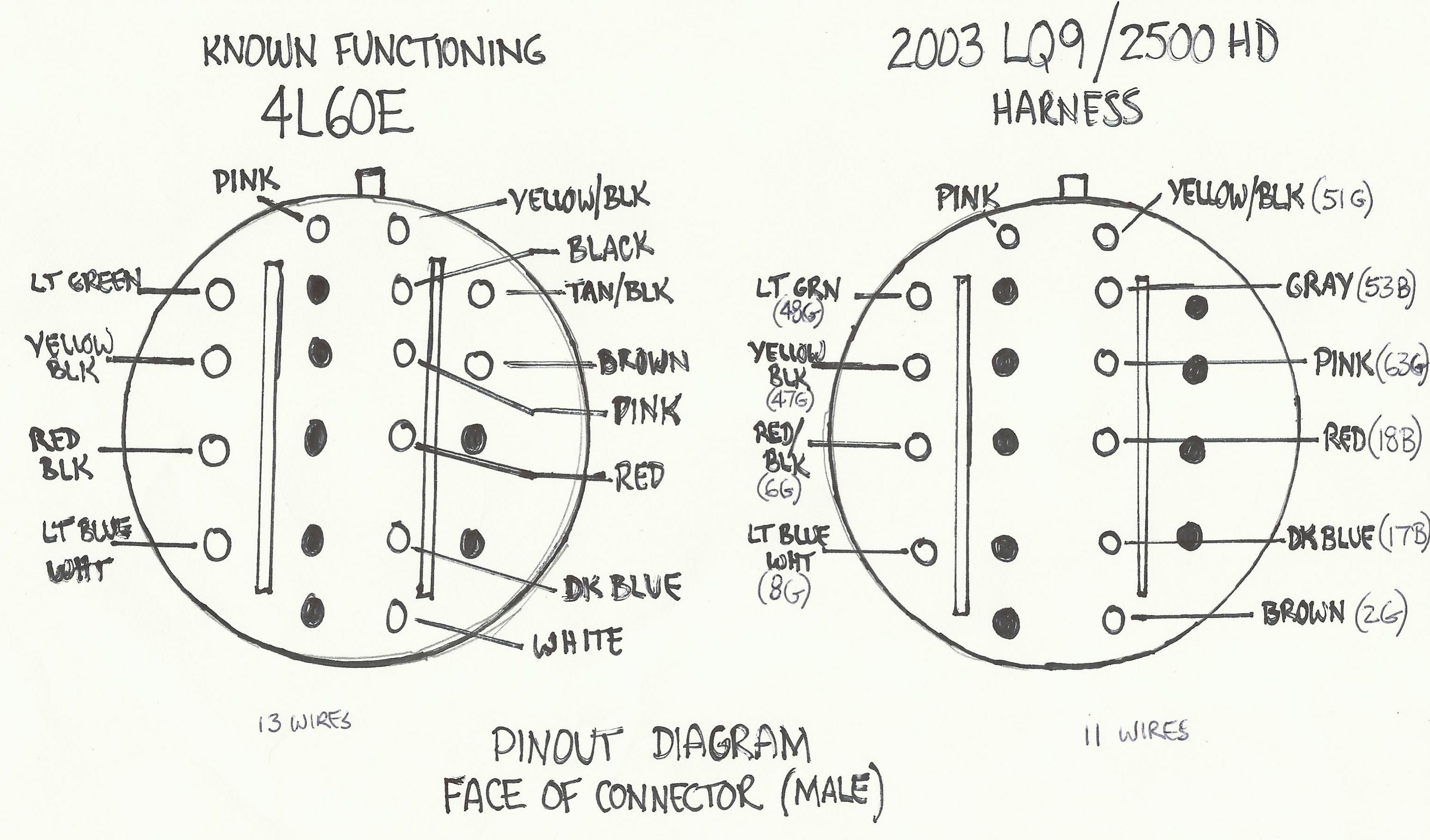
4l60e tcc wiring diagram
The 4l60e transmission was found in a many light and medium duty GM cars, trucks, and SUV's from the mid-1990's all the way up to the early 2010's. Here is the complete list of 4l60e equipped cars and trucks. Buick Rainier 2004-2007 Buick Roadmaster 1994-1996 Cadillac Escalade 1999-2000, 2002-2005 (models with LM7/5.3L V8 Also with 6.0 LQ9)
[DIAGRAM] 4l60e Transmission Line Diagram
The 4L60e transmission is an electronically operated 4-speed transmission designed for vehicles with longitudinal engines. It utilizes four forward gears and one reverse gear and has a vehicle weight rating of 6000 lbs. Before adding the recommended 4L60e transmission fluid, this transmission weighs 146 lbs.

4l60e line pressure chart
4l60e Identification Diagram - How To Identify 4l60e Transmission 4l60e Case Identification Diagram Sticker ID informtaion found on the top of the case: 1 - 4 = 2004 2 - Model 3 - Hydra-Matic 4L60-E 4 - Transmission Asm. as Shipped Number 5 - 4 = Model Year 6 - Julian Date or Day of the Year
What is the meaning of S2 and L1 in automatic transmission? Quora
Pressure testing transmission Gauge port location, use 0-400 psi gauge Reverse: 64-324 psi (min/max) Park, neutral, drive ranges 55-189 (min/max) The folowing chart can be used to determine pressure using scanner to command pressure at all settings to determine epc function/pump and internal leaks. MLPS switch states
9+ 4l60e transmission vacuum line 4l60e vent hose diagram LorrenReiley
The 4L60E transmission vacuum line diagram is a detailed schematic of the vacuum lines used in General Motors (GM) vehicles equipped with the 4L60E transmission. It shows the routing of all of the vacuum lines, their locations, and their connections to various components.
4l60e how many springs in 12 shift accumulator? Chevy Silverado and
4l60e Transmission Cooler Lines Diagram - Signs Of Trouble February 10, 2023 by Robert Walker Heat in operation is always a potential threat to the engine. That's why more and more car owners want to learn about the 4l60e transmission cooler lines diagram to know how to use it effectively. What does that include? Scroll down and find the answer.
55+ 4l60e transmission vacuum line 4l60e vent hose diagram JhodiEllisa
Dexron VI. The 4-speed family of GM transmissions named as TH700R4 (Turbo-Hydramatic) 4L60E/ 4L65E has been launched in production in 1982 and after some minor changes was renamed as 4L60. This 4-speed transmission for RWD cars was constructively based on the popular HydraMatic 700R4, but produced at the GM factory in Toledo (Ohio) and proved.

New Of 4l60e Transmission Shift Solenoid Wiring Diagram What Turns
4L60E: Top 4L80E: Lower Front 4T40/5: Bottom 4T40E: Lower 4T60E, 4T65E: Horizontal Case Fitting 4T80E: Main Case Fitting ECVT (Not Channel Plate) 400, 375, 475 (3L80, 3L80H) Top 425:. Line Going to the Transmission Case: Lineartronic CVT Lower line: TOYOTA: Transmission: Location FWD: All (Except Tercel A55 & A55F) Bottom Tercel A55 & A55F.
4l60e Transmission Line Diagram My XXX Hot Girl
The 4L60E (and similar 4L65E) is a series of automatic transmissions from General Motors. Designed for longitudinal engine configurations, the series includes 4 forward gears and 1 reverse gear. The 4L60E is the electronically commanded evolution of the Turbo-Hydramatic 700R4, originally produced in 1982.

4l60e Transmission Line Diagram
Reduce Harsh 1-2 Shift Damage. Damage to the band, input/output shafts, sprag, etc. can be reduced by properly cushioning the large ratio change on the 1-2 shift: Never use a 1-2 servo that eliminates the cushion spring. Never reduce the 1-2 accumulator piston stroke. Never leave out the 1-2 checkball.
4l60e Valve Body Bolts Diagram CPT 4l60e
Transmission Diagrams Page 14 Optional Features Page 16 Manual Shift Connections Page 18 Shiftware Page 22 Important Information Page 25 Troubleshooting Page 26 Contact Page 28 READ BEFORE PROCEEDING Before installing the Quick 1 unit, we recommend you read the manual from beginning to end.
[DIAGRAM] Allison 1000 Transmission Fluid Flow Diagram
4L60E 4L60E Automatic Transmission Parts , Transmission Parts Selection. 5/16" LINE: 4L60E, 4L80E (NOT 4L80E REAR 97-UP USE #34996EA) image #996 Item #D74996B: $7.00. SEAL KIT Cooler Line Clips (2) and O-Rings (2) for 5/16" Snap in Cooler Line Fitting. TRANSMISSION DIAGRAM Automatic Transmission Parts
4l80e exploded diagram
Chevy Transmission Cooler Lines Diagram Robert September 8, 2022 If you're working on your Chevy and need a Transmission Cooler Lines diagram, you're in luck. We've got a great one right here that will help you get the job done quickly and easily. Just take a look and you'll see what we mean.

35 4l60e Transmission Cooler Lines Diagram Wire Diagram Source
Helps cure: Low line pressure High line pressure 4L60, 4L60-E, 4L65-E, 4L70-E, Powerglide, TH350C, TH400 Stator Support Bushing 35007A Bushing Style: Precision Material: Steel-backed copper alloy Width: 0.500" Housing Bore: 1.121" Inner Dia.: 1.004" Shaft Dia.: 1.002" Helps cure: Bushing wear Bushing failure 4L60-E, 4L65-E, 4L70-E
