14+ Transistor 5000W Audio Amplifier Circuit Diagram Robhosking Diagram

Simple Audio Amplifier Circuit Diagram using 555 Timer IC
High Fidelity or HiFi is a term used by home stereo listeners, audiophiles, and home audio enthusiasts to refer to high-quality reproduction of sound to distinguish it from the lower quality sound produced by inexpensive audio equipment.

Audio Amplifier Circuit Diagram With Layout Pdf 1600W High Power Amplifier Circuit complete
Section 5.1 Power Transistors & Heat Sinks. • Power Transistor Construction. • Power De-rating & High Power Operation. • Thermal Resistance of Heat Sinks. • Thermal Runaway. Section 5.2 Class A Power Amplifiers. •The limitations due to the efficiency of class A power amplifiers. •Transformer coupled Class A power output stages.

Mic Pre Amplifier using IC 4558 Electronic Circuit
DESCRIPTION The LM3886 is a high-performance audio power amplifier capable of delivering 68W of continuous average power to a 4Ω load and 38W into 8Ω with 0.1% THD+N from 20Hz-20kHz. The performance of the LM3886, utilizing its Self Peak Instantaneous Temperature (°Ke) (SPiKe)
New Audio Amplifier Circuit Diagram With Layout Pdf Wiring Diagram
Section 4.1 Input Compensation. • Describe typical input correction circuits. Section 4.2 Amplifier Controls. • Describe typical tone control circuits. Section 4.3 Amplifiers and Impedance. • Describe typical circuits for controlling impedance. Section 4.4 NFB Quiz.

600W Audio Amplifier Circuit with 2SC5200 2SA1943 and PCB Subwoofer amplifier, Audio amplifier
Introduction This is the first of two articles on audio circuits. New oper-ational amplifiers from Texas Instruments have excellent audio performance and can be used in high-performance applications. There have been many collections of op amp audio circuits in the past, but all of them focus on split-supply circuits.
Simple 100W HiFi Audio Amplifier Circuit Diagram Electronic Circuits Diagram
By using a schematic and following the designated paths created by the diagrams in the 12v 400w audio amplifier circuit diagram pdf, assembly of these components is relatively straightforward. When connected correctly, the circuitry leverages the power supply to amplify the signals sent to the speaker, resulting in a powerful sound output.
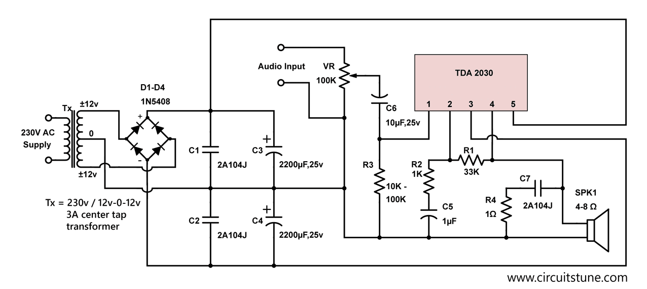
Electronic Schematic Circuit Diagram CircuitsTune
8.1 Overview. The LM386 is a mono low voltage amplifier that can be used in a variety of applications. It can drive loads from. 4 Ω to 32 Ω. The gain is internally set to 20 but it can be modified from 20 to 200 by placing a resistor and capacitor between pins 1 and 8.
14+ Transistor 5000W Audio Amplifier Circuit Diagram Robhosking Diagram
Audio amplifier is the basic circuit configuration that is required to amplify, the audio signal received through a device like a microphone or the audio signal that is to be transmitted out through a speaker/ Radio device/Wireless transmitter etc.
13+ D1047 Amplifier Circuit Diagram Robhosking Diagram
Below is the schematic diagram given for this LM386 IC based audio amplifier. Resistor R2 (10k) has been used as a Pull up resistor to connect Condenser mic to the positive supply voltage, to provide the power to the mic. A suitable resistor should be used for proper working of mic, you can look up to datasheet for the value or use a variable.
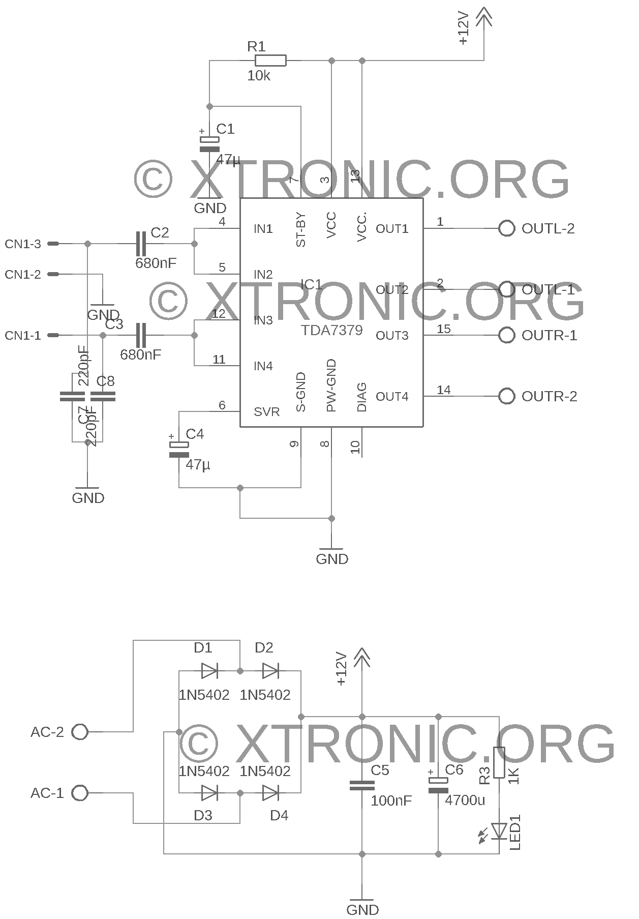
TDA7379 Amplifier Circuit Diagram 2x 38W Xtronic
circuits-power audio amplifiers, due to their advantages - schematic simplicity, small dimensionss, large range of output powers, polyfunctionality. For correct usage of integrated circuits of the power audio amplifiers, irresepective of a field of application, it is necessary to know following: - Function of integrated circuit;
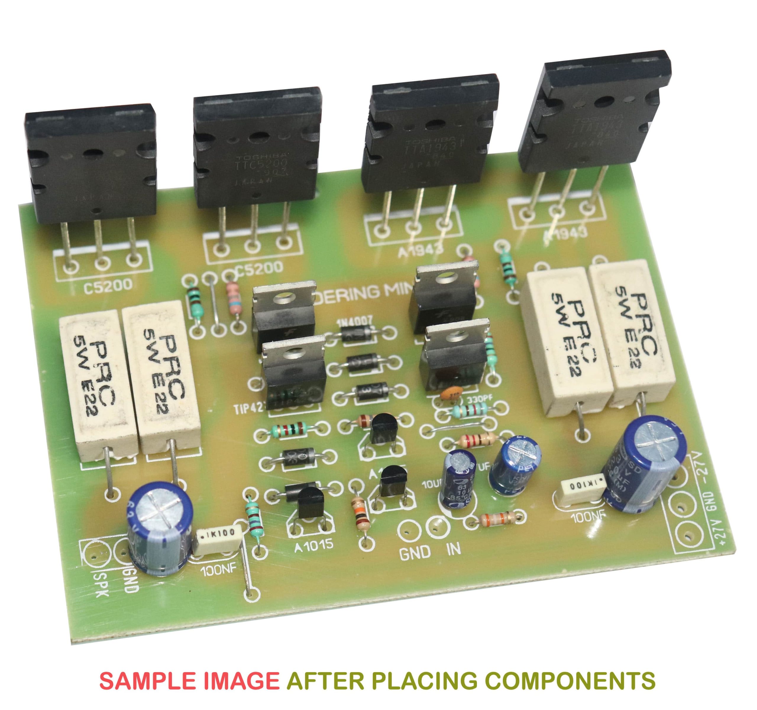
2sc5200 2sa1943 amplifier circuit diagram Soldering Mind
Audio Amplifier Circuit Overview In the first part of lab#1 you will construct a low-power audio amplifier/speaker driver based on the LM386 IC from National Semiconductor. The audio amplifier will be a self-contained, battery-operated component.

Circuit Diagram Of Audio Amplifier Of 12v Pdf champion
Audio amplifier PCB design Crosstalk Rail induction distortion The mounting of output devices Single and double-sided PCBs Power supply PCB layout Power amplifier PCB layout details The audio PCB layout sequence Miscellaneous points Amplifier grounding Ground loops: how they work and how to deal with them Hum injection by mains grounding.
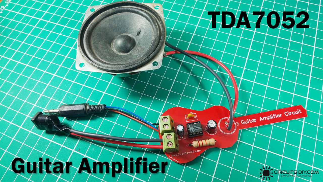
Audio Amplifier Circuits — Circuits DIY
In an amplifier circuit, the LM386 takes an audio input signal and increases its potential anywhere from 20 to 200 times. That amplification is what's known as the voltage gain. Gain vs Volume

Professional Audio Amplifier Schematic Diagram Circuit Diagram
Audio power amplifiers are used to deliver a large amount of power to a low resistance load. Typical load values range from 300 Ω (for transmission antennas) to 8Ω (for loudspeakers). Although these load values do not cover every possibility, they do illustrate the fact that audio power amplifiers usually drive low-resistance loads.

100 watts subwoofer amplifier circuit diagram Subwoofer amplifier, Amplifier circuit, Circuit
Abstract and Figures. This paper reports the design and implementation of a 300Watt audio amplifier. The system features also include an LCD. The circuit analysis is presented and procedures for.

How to make Audio Amplifier Circuit Using 555 Timer
This effectively transfers signal splitting from the sub-amplifiers to a separate part of the circuit." From Peter Blomley (PDF). The end result of this difficult-to-understand circuitry (we are used to voltage circuits) is a Class B amplifier that has a distortion lower than 0.1% with no feedback at all.
